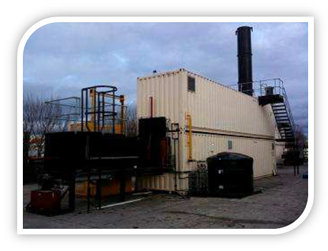
For the manufacture and supply of five automatically loaded Pyrotect G250 General, Clinical and Medical Waste Incinerator. Being specifically designed for the safe and economical destruction of general type wastes
Each system has primarily been designed for the general waste disposal needs of oil Field drilling and production sites set in outlying/remote locations.
The majority of the entire plant is of a fabricated mild steel construction using a combination of Mild steel plate and mild steel stiffening sections. Any part of the plant that is subjected to the Heat generated by the incineration process is also lined with fully insulating refractory materials..
As noted above each system may be configured to destroy a wide variety of wastes. Whilst not Exhaustive the following list gives an indication of the waste types that may be processed
| Medical wastes | Field Camp wastes | Hazardous wastes |
| Theatre wastes | Industrial wastes | Waste solvents & paints |
| Ward wastes | General wastes | Waste oils & lubricants |
| Pharmaceuticals | Municipal wastes | Contaminated wastes |
| Pathological wastes | Packaging wastes | Radioactive wastes |
A dedicated waste bin lifting and tipping unit configured To accept and decant industry standard 1100 liter waste Bins
A fully automated hydraulically powered ram feeder unit Configured to transfer the tipped wastes into the primary Combustion chamber of the incinerator

A low level combustion chamber where the incineration Of the waste material takes place
A high level combustion chamber where the flue gases Produced by the incineration process are thoroughly Oxidized and treated in a high temperature environment.
A high level vertical chimney from which the colorless And odorless flue gas is exhausted
An integral ash ram that automatically maneuvers the Ash residues towards the discharge zone
A fully automated ash removal system that extracts the Ash residues on a daily basis
Two pre-owned 40’ shipping containers are used to house the majority of the equipment. These have been suitably modified to accept the two combustion chambers of the incineration system and the appropriate ancillary components.The two containers are stacked, as shown, with the main burning chamber (primary combustion chamber) being located within the lower container and the after-burning chamber (secondary combustion chamber) being positioned within the upper container. The lower sections of the chimney including its base are also located within the latter.The two containers would be utilised for the delivery of the equipment

Each unit is fitted with automatic package burners, all of which are configured for dual fuel (fuel Oil or natural gas) operation. Each burner package is complete with electric ignition and flame Failure control devices and all of the required valves, motors and pumps as well as an integral Continuously running air fan. They are automatically temperature controlled to provide optimum Combustion conditions, adequate secondary chamber temperatures and fuel economy.
Each unit is fitted with two independently controlled combustion air systems, which provide the Required levels of oxygen for the correct operation of the process. The combustion air is Provided by automatically controlled centrifugal fans, which direct the air to strategically located Injection points within the respective combustion chambers. This fine control ensures that the Optimum combustion conditions prevail during the complete incineration process.
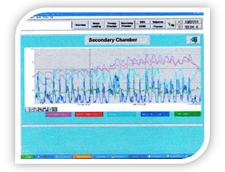
Each unit is fitted with a continuous emission monitoring system that provides an instantaneous Display of the levels of Carbon Monoxide, Oxygen and Particulate Matter entrained within the Flue gas. The data from the respective monitors is relayed to the main control system where it is Then utilized to effect any required changes to the combustion parameters, including the control Of the secondary combustion air delivery rate. Additional data signals are then generated by the Main control system PLC and are transferred to the separate SCADA system terminal screen.
Each unit is fitted with an automatic control system that is built to IEC Standards. Each system
Incorporates a main PLC controller that provides for the fully automated control of the plant
Functions and incorporates the following sequences
1. Preheat Cycle
2. Burn Cycle
3. Loading Cycle
4. Burn down Cycle
5. Cool down Cycle
The control system facia is equipped with a
Series of indicators showing the operational
Status of the plant together with the indication
Of the combustion chamber temperatures. The
Control system is also enhanced by the
Addition of a computer based SCADA system
That provides and records a detailed overview
Of the plant operational data within a separate
Or remote control room/supervisors office

Each system is complete with single point connections being provided for each of the required Utilities. These are as follows:
The electrical supply is terminated at a main distribution board located within the lower container Housing. This provides for one single connection of the incoming supply, which may be from a Permanent source or a local generator. The required supply is 380/440 V, 3 Phase and Neutral,50/60Hz. All of the required sub-circuit wiring, from the distribution board to the various points Within the housings, is included as part of the complete package. The various outlet points Within the housings include:
The main incinerator control panel
Internal and external lighting
Internal power points
Internal ventilation fans
The light oil fuel supply is taken from an externally positioned storage vessel that has a nominal Capacity of 2500 litres. This level of fuel oil will allow 7 to 10 days of normal operation of the Plant, dependant upon the waste types. All of the required distribution network (circulation Pumps and pipework), from the vessel to the burner systems, is included as part of the complete Package.
The natural gas supply is taken from a single, externally positioned, termination point where the Incoming supply may be connected. All of the required distribution pipework, from the Termination point to the burner systems, is included as part of the complete package.
The water supply is taken from an externally positioned storage vessel that has a nominal Capacity of 1200 liters. All of the required distribution network (circulation pumps and pipe work),From the vessel to the incinerator and waste loading systems, is included as part of the complete Package